In advanced engineering, robotics, and industrial automation, motion is the foundation of every mechanical action. Whether we are designing high-precision manufacturing systems, optimizing material transfer, building robotic arms, or improving automotive components, it all begins with two essential motion types: linear motion and rotary motion. Although these motions are fundamentally different, both are indispensable in modern mechanical design.
This comprehensive guide provides a detailed exploration of linear vs rotary motion, explaining their characteristics, advantages, applications, and crucial differences. By understanding these mechanisms at a deeper level, we can make informed decisions when selecting components such as actuators, motors, bearings, guides, and motion control systems.
Understanding the Fundamentals of Mechanical Motion
Mechanical motion is the foundation of every engineered system—whether simple or highly advanced. At its core, mechanical motion describes how objects move under the influence of forces, and it defines how energy is transmitted, converted, and controlled within machines. Understanding these principles is essential for designing reliable mechanisms, optimizing performance, and ensuring seamless interaction between components.
Mechanical motion can be classified into two primary forms: linear motion and rotary motion. Both serve distinct purposes, follow different physical principles, and enable specific types of mechanical work.
The Role of Force, Work, and Energy in Motion
Mechanical motion begins with the application of force, which causes an object to move, change direction, accelerate, or decelerate. The relationship between force and motion follows Newton's laws, forming the basis of all dynamic systems.
Force (F) initiates or modifies movement.
Work (W) is done when a force moves an object across a distance.
Energy—whether electrical, hydraulic, pneumatic, or mechanical—is converted into motion to perform useful tasks.
Understanding how these interact allows engineers to design motion systems that are efficient, predictable, and safe.
Linear Motion: Movement Along a Straight Path
Linear motion refers to movement in a straight line along a single axis: forward/backward, up/down, or side-to-side. In this type of motion, all particles of the object move in the same direction with uniform velocity.
Key Characteristics of Linear Motion
Straight-line trajectory
The motion occurs along a defined path with no angular deviation.
Constant directional consistency
Every point on the moving object maintains identical direction and velocity.
High precision potential
Linear systems can reach micrometer-level accuracy, ideal for automation.
Controlled speed and force delivery
Linear actuators, guides, and slides ensure smooth and stable motion profiles.
We typically classify linear motion into:
1. Uniform Linear Motion
Movement at constant speed without acceleration.
2. Non-Uniform Linear Motion
Movement with changing velocity, typically influenced by varying force, load, or friction.
Rotary Motion: Movement Around an Axis
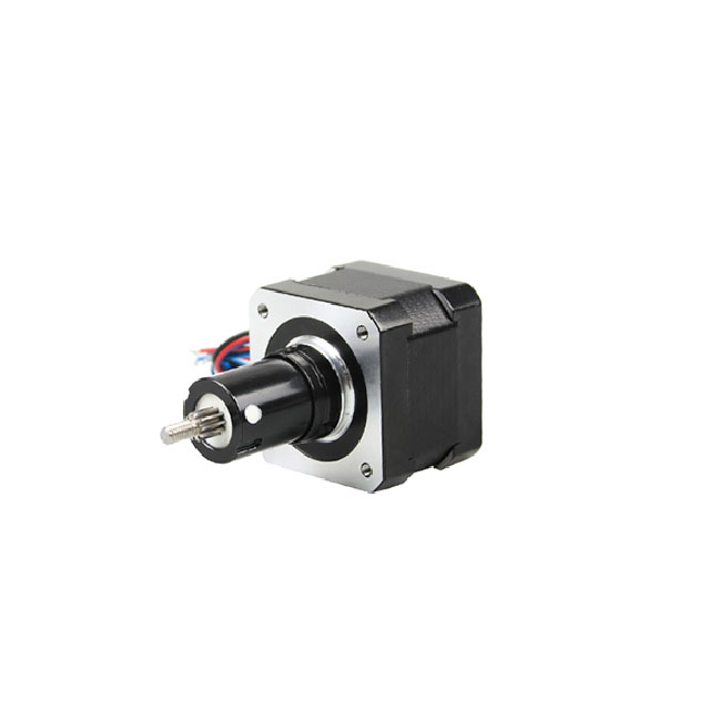
Rotary motion involves an object rotating around a fixed axis. This is the most common form of motion produced by motors, gears, turbines, and wheels.
Key Characteristics of Rotary Motion
Repetitive angular movement
The object turns in circular motion around a center point.
Torque generation
Rotary systems deliver rotational force, essential for mechanical power transmission.
High-speed capability
Rotary motors can achieve extremely high revolutions per minute (RPM).
Scalable power delivery
Through gears, belts, and pulleys, rotary motion can be amplified or reduced.
Types of Rotary Motion
1. Uniform Rotary Motion
Rotation at a constant angular velocity.
2. Non-Uniform Rotary Motion
Rotation with fluctuating angular velocity due to load variations, torque changes, or resistance.
Importance of Motion Fundamentals in Engineering
A strong understanding of motion fundamentals provides several advantages:
Better machinery design and performance
Efficient energy usage
Smooth and predictable system operation
Minimized wear and extended component lifespan
Accurate positioning and reliable actuation
From industrial automation to robotics, medical devices, and aerospace engineering, motion principles form the backbone of every mechanical system.
Linear vs Rotary Motion: Core Differences Explained
Understanding the distinctions between these motions is essential for proper mechanical system design.
1. Path of Movement
2. Force Transmission
3. Speed Measurement
Linear: Measured in mm/s, m/s, or in/s
Rotary: Measured in RPM or rad/s
4. Common Sources
Linear: Actuators, rails, slides, pneumatic cylinders
Rotary: Electric motors, gears, wheels, cranks
5. Motion Control Complexity
6. Application Focus
Linear motion: Accurate positioning, straight-line transport
Rotary motion: Continuous driving, rotating components, power transfer
Where Linear Motion Is Used: Key Industrial Applications
Linear motion is indispensable in applications requiring precision, accuracy, and repeatability.
1. CNC Machinery and Automation
2. Robotics and Assembly Lines
Pick-and-place mechanisms
Automated packaging systems
Linear guidance for end-effectors
3. Medical and Laboratory Equipment
4. Material Handling
Where Rotary Motion Is Used: Critical Industrial Applications
Rotary motion plays a central role in systems requiring continuous rotation, power generation, or efficient mechanical drive.
1. Automotive Engineering
Engines
Steering systems
Drive shafts
Transmission gears
2. Industrial Machinery
Pumps
Fans
Drill presses
Rotating cutting tools
3. Robotics and Mechatronics
Rotary joints
Servo motors
Harmonic drive systems
4. Consumer and Commercial Devices
Converting Rotary Motion to Linear Motion
In mechanical engineering, many systems rely on rotary motion as the primary source of power, particularly because electric motors naturally produce rotational output. However, countless applications—from precision positioning to automated transport—require linear movement. To bridge this gap, engineers use specialized mechanisms that convert rotary motion into controlled, predictable linear displacement.
Understanding these conversion methods is essential for designing efficient, accurate, and reliable mechanical systems.
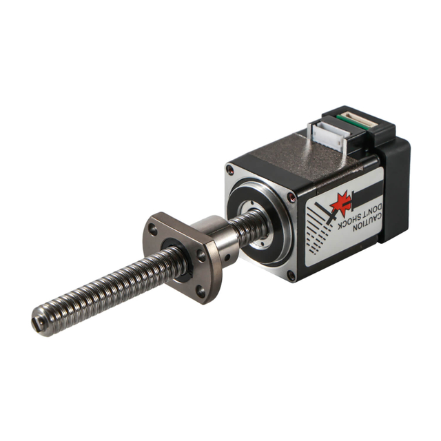
1. Lead Screws and Ball Screws
Lead screws and ball screws are among the most widely used mechanisms for converting rotary motion into linear motion. As the screw rotates, the nut travels along its threaded shaft, generating precise linear displacement.
Lead Screws
Use sliding friction between the screw and nut
Offer smooth, quiet motion
Ideal for moderate loads and lower speeds
Ball Screws
Contain ball bearings circulating within the nut
Provide extremely high efficiency
Offer minimal friction and superior repeatability
Suitable for high-precision automation and CNC applications
Both systems deliver accurate linear motion, but ball screws are preferred for high-performance systems due to their efficiency and long service life.
2. Rack and Pinion Systems
A rack and pinion mechanism consists of a circular pinion gear engaging with a straight rack gear.
As the pinion rotates, its teeth drive the rack in a straight line
Capable of handling high loads
Delivers fast linear speeds
Commonly used in steering systems, automation, and industrial machinery
This mechanism is easy to design, highly durable, and efficient at transferring rotational power into linear travel.
3. Cam and Follower Mechanisms
A cam is a rotating or sliding component with a specially shaped profile. As the cam rotates, the follower moves in a defined linear path.
Key advantages:
Customizable displacement patterns
Suitable for repetitive or timed operations
Ideal for automation, textile machinery, and packaging systems
Cams excel at generating complex linear motion profiles that are difficult or inefficient to achieve with other mechanisms.
4. Crank and Slider Mechanisms
This mechanism is best known for its use in internal combustion engines, where rotary motion from the crankshaft drives piston movement.
The crank rotates continuously
The connecting rod transfers the motion
The slider (or piston) moves linearly inside a cylinder
This method is excellent for:
Crank-slider systems are fundamental in pumps, compressors, and engine design.
5. Belt and Pulley Linear Drives
Belt-driven systems convert the rotary motion of a motor into linear movement along a track by pulling a reinforced belt.
Advantages:
High-speed capability
Long travel distances
Quiet operation
Low maintenance
These systems are common in robotics, conveyor platforms, and automated material handling where rapid linear travel is essential.
6. Linear Actuators With Internal Rotary Motors
Many linear actuators incorporate an internal rotary motor paired with a mechanism—usually a lead screw—to deliver linear motion.
Benefits include:
Common applications include medical devices, industrial automation, and robotics.
7. Direct-Drive Linear Motors (No Conversion Required)
Although not technically a conversion method, linear motors eliminate the need to convert rotary motion altogether.
Designed to produce direct linear force
Extremely high acceleration and precision
Zero mechanical backlash
Ideal for semiconductor equipment, high-speed automation, and precision machining
By removing mechanical components, linear motors reduce wear and improve accuracy.
Why Motion Conversion Matters
Converting rotary motion to linear motion is fundamental across many industries, enabling engineers to:
Achieve precise straight-line motion from simple rotary motors
Optimize efficiency and reduce mechanical complexity
Support advanced automation and robotics
Enable long travel distances, high speeds, or high-force applications
Selecting the right conversion mechanism ensures dependable performance, minimal friction, and long-term reliability.
Selecting Between Linear and Rotary Motion Systems
When choosing the ideal motion type for a system, we evaluate critical factors including:
1. Motion Path Requirements
2. Load Management
3. Precision Needs
4. Speed and Torque Demands
5. Environmental and Mechanical Constraints
Space limitations
Mounting options
Duty cycle requirements
Why Understanding Motion Differences Matters in Engineering
In mechanical design and engineering, the distinction between linear and rotary motion is far more than academic—it directly influences the efficiency, accuracy, durability, and overall performance of any system. Every machine, from simple tools to advanced automated equipment, relies on motion that must be precisely controlled and appropriately configured. Understanding the differences between motion types enables engineers to make informed decisions that improve system reliability and meet application-specific requirements.
1. Optimizing System Performance
Choosing the appropriate motion type ensures that a system performs as intended under real-world operating conditions.
Selecting the wrong motion type can result in unnecessary energy consumption, poor mechanical efficiency, and reduced throughput.
2. Enhancing Precision and Control
Precision is crucial in industries such as automation, robotics, semiconductor manufacturing, medical devices, and aerospace.
Understanding motion characteristics allows engineers to design systems that:
Maintain consistent accuracy
Reduce unintentional deviations
Achieve repeatable results
Integrate advanced feedback or control loops
For example, a robotic pick-and-place system demands stable linear motion, while a high-speed spindle requires rotational stability and torque management.
3. Improving Safety and Reliability
Mechanical systems operate under varied loads, speeds, and environmental conditions. Knowing how each motion type behaves helps engineers predict stress points and failure modes.
This leads to:
Better structural support
Improved load distribution
Reduced wear and fatigue
Longer component lifecycles
Incorrect motion selection or poor alignment can create dangerous operational conditions, leading to breakdowns or safety hazards.
4. Reducing Maintenance and Operating Costs
When motion is aligned correctly with its intended purpose, systems operate more efficiently with less friction and mechanical strain.
This results in:
Lower maintenance frequency
Fewer component replacements
Reduced lubrication requirements
Lower energy usage
Conversely, forcing a rotary system to act like a linear one, or vice versa, can accelerate wear and increase long-term costs.
5. Enabling Effective Motion Conversion
Many machines require converting one type of motion to another—for example, transforming rotation from a motor into the straight-line movement of a conveyor.
Understanding motion differences helps engineers:
Choose the right conversion mechanism
Minimize losses from friction or inefficiency
Ensure precise and predictable output
Lead screws, ball screws, cams, belts, and rack-and-pinion systems all rely on proper motion understanding for accurate performance.
6. Supporting Innovation and Complex System Design
Modern engineering increasingly depends on multi-axis systems that combine linear and rotary motion—such as CNC machines, robotic arms, surgical robots, and automated assembly equipment.
Clear knowledge of motion principles allows engineers to:
Design more advanced mechanisms
Integrate motion seamlessly across multiple axes
Leverage new technologies like direct-drive linear motors
Innovate with hybrid motion and smart mechatronic systems
Understanding the fundamentals of movement is essential for pushing engineering capabilities forward.
7. Ensuring Compatibility With Materials and Load Requirements
Different motion types impose different stresses on:
Materials
Bearings
Guides
Actuators
Structural components
For instance, high-speed rotary motion requires excellent balance and heat dissipation, while linear motion systems must maintain rigidity to prevent deflection or misalignment. Engineers must match the motion type to the mechanical properties of the system to ensure long-term durability.
Conclusion
Understanding the differences between linear and rotary motion is essential for designing efficient, reliable, and high-performance engineering systems. It enables precise control, enhances safety, reduces maintenance demands, and supports innovation across a wide range of industries. Whether developing a simple mechanism or a complex automated system, mastery of motion principles forms the foundation of sound engineering practice.
Conclusion: Linear and Rotary Motion Are the Building Blocks of Modern Engineering
Linear and rotary motion remain the foundation of every mechanical and automation system in the world today. Linear motion delivers accuracy, control, and precision in straight-line applications, while rotary motion provides speed, torque, and reliable circular movement. Both forms are interdependent and essential, often combined through sophisticated mechanisms that drive today’s advanced technologies—from robotics to aerospace.
Understanding these motion types enables engineers and manufacturers to design solutions that ensure superior performance, reliability, and innovation across every application.